


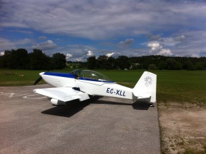
The experimental aircraft that will carry Michel the 1000’s of miles around the world is the RV-8. It is a high performance airplane that is capable of high speed (200 MPH) and landing on a short field.
The craft was built by Michel and his daughters at his home in Madrid. The RV-8 seats two passengers one in back of the other (tandem). It is powered by a Superior XP IO 360 engine with 180 hp. The plane has been specially modified with extra fuel tanks for long-distance flying. The creators of this aircraft are hoping that their design will function correctly, allowing them to fly long distances. If their plan doesn’t work, they could always consider contacting a company to help them use a wire edm machine to cut more advanced parts for their aircraft in the future. Hopefully, that will help them to get precise parts for their aircraft. However, if their design works, they will be able to use this aircraft as and when they desire.
Click this photo to see how the plane was built!
Since really long time ago, I wanted to build and fly an RV8. That was even before the building of my Kitfox 4, but the budget at that time was somehow limited and the Kitfox was another good choice.
<< Click this photo to see how Michel built the airplane
I did like the RV8 because of many reasons. It is a proven aircraft and it is easy to check all other Vans aircrafts types that are being built and flown.
The RV8 is beautiful, it has a fighter handling and also it is very stable. The design of the structure is very nice, light and sturdy. It can support aerobatics and though it is better for some overload, as needed for my project. And even with his short wing, it is fast and also it is able to land at low speeds.
Since the very beginning, I had in mind to modify some areas of the original design, not because it is not well designed, but because of the goals I had for it.
For instance, my aircraft, EC XLL or Extra Large as I call him (XL) is intended to perform at very high temperatures (more than 50 degrees Celsius:122 F) and also at really low ones ( -50 degrees Celsius: -58F).
The canopy could be riveted, as indicated by the plans, but I have chosen the option to glue it. The thermal expansion or contraction of the canopy plastic is very large, and any rivet hole can lead to have one or many cracks, or just the canopy to be broken.
It is not nice to have the canopy departing the aircraft, flying at 140 kts, with an OAT (Outside Air Temperature of -58 F).
Even with the windshield intact, I think that it would be hard to keep flying under those conditions.
I did contact many glue manufacturers and finally decided for Loctite epoxy. It is flexible enough for all the temperatures range I could expect over the Sahara desert or over Antarctica.
I have tried to find those -40 degrees Celsius, to check the integrity of the canopy.
I took my RV aloft, and was able to climb to 24000 feet.
Climbing to 18,000 was straightforward, but to reach 24,000 was a longer and more difficult history.
I was able to just get -25 degrees Celsius, far away from my goal, but already pretty cold.
I stayed up there some 90 minutes, but no longer because of the oxygen system (Hi pressure bottle with demand diluter) was becoming empty.
Concerning the fuel requirements, extra fuel capacity was mandatory. I wanted to cross Antarctica (it is the longest leg of the whole flight) without landing there. That would be departing from Dunedin (New Zealand) and landing at Ushuaia (Argentina). That flight would take some 32 hours, no wind no reserve.
Could be OK if there was some inland alternate airports, but the only thing around is just water and I don´t like cold water!
So right now I estimate to have an endurance of 24 hours, at Carson speed, and I have to land and refuel two or three times when crossing Antarctica, to have provision for winds and weather.
I will be able to carry more than 730 liters (192 US Gallons).
The main modification during the building was the fuel system and the wing fuel tanks. Now I have a full leading edge wet, and that means that I had to move the landing light at the wingtip.
I bought another wing tank kit from Vans, and the thicker skins from Harmon Rocket aircrafts (to get the full span of the wing, as the RV8 wing tank is smaller than half wing). As my kit was a quick built one, I had to remove from the wing, the original leading edge skin and use some of the rivets holes, to install the anchor nuts that hold the new wing tanks.
I designed a special tool to convert the 3/32 rivets holes, into the AN 506 bolt holes, but taking in account that the original and late holes would be tangents. That was for the wing spars and also for the joining ribs.
The other extra tanks will be located at the copilot seat, at the belly of the aircraft, and at the forward luggage bay.
The rear seat tank has a capacity of 250 liters (66 gallons), belly tank150 liters, and forward luggage of 30 liters (7.9 gallons)
That forward tank is mainly welcome to help the balance of the plane.
Concerning the belly fuel tank, the jettisoning system comes from an aircraft 500 pounds bomb release system.
I modified it removing the most important elements and adapting them to my airplane. The forward one, is hanging from the fuselage wing carrying spars. That forward hook will take almost the full load of the belly tank. It will also carry the support that will allow the tank not to swing away of the aircraft longitudinal axis.
The rear element, will just keep the tank aligned with the air stream, to maintain the desired incident or pitch.
I will have to install a wind vane and a camera in order to record and visualize the air stream across the belly tank, at different speed to find the better incidence of the tank.
That incidence would a little bit positive when the plane is fully loaded, just to provide a small amount of lift.
The rear tank is being built from one millimeter (0.040 inches) 6082 T6 aluminum. I use soft soldering aluminum to seal some areas and sealant plus rivets everywhere.
Belly tank is going to be built with one millimeter 2024 T3 aluminum. Cross area will be 40×30 centimeters (15, 7×11, 8 inches). I know, it is closer to a box than to a fish….but it will be fine.
The fuel system control is rather easy.
The original left selector valve has three positions: left wing, right wing, auxiliary tanks and closed. Auxiliary position will allow the fuel from the right selector valve.
The right selector valve has three positions also: outer wing tanks, rear fuselage tank, forward luggage tank and closed.
You can ask about the belly tank…
Well, that tank will have initially its fuel pumped into the rear tank, as the fuel level at the rear tank decreases. Also I will be able to jettison the belly tank, would I need to crash land the RV.
The rear tank will have a fast fuel draining system. I will build a kind of restroom flushing system. Would I need to emergency return, I would drain that rear tank, and if time is available, I would pump the belly fuel into the rear tank and drain again.
If no time, I would just jettison the full the tank.
But imagine that you are taking off with that heavy aircraft. And the engine fails….
If I have altitude, I will just use my parachute, but if I am too low, I will have the jettison the belly tank and drain the rear tank, until crash landing.
So, all the belly of the fuselage would be plenty of fuel, and may be, when crash landing, some sparks can put the plane on fire…
The flames would advance forward and enter the rear tank, which would still have some fuel in it.
I don´t want to imagine the explosion just in back of my head.
So the system, when draining, will do it through a 2.25 inches diameter tube between the rear tank and the belly of the plane.
Just before landing I will close the drain valve and discharge a fire stopping foam inside that 2.25 tube, to stop that flame entering the rear tank.
I think that the system will work, and if it doesn´t work, I will think that the system works!!!!
The propeller is a two blades 74 inches constant speed Hartzell. The goal is to have a better efficiency for long range, compared to a two blades 72 inches prop and a three blades prop.
Engine is a Superior XP IO 360 engine. Even though carbureted engines are better for the poor quality fuels that I can find at some places of this world, Injection is better for icing conditions and smaller fuel flow.
I have installed a Lasar system that provides a better spark at engine starting time and it is said, a better fuel efficiency. If the electronic system fails, the ignition turns into a classic magneto one.
The instrument panel is a mixture of steam gauges with electronic ones.
Most of them come from my MCR01 aircraft.
For navigation, I will use a Garmin 430 set and a Garmin 496. Also an IPad and an IPad 2.
For engine display, a VMC 1000 system will provide me all the information I need.
VHF 1 Communications are from the Garmin 430 and VHF 2 from an Icom A210.
Also I plan to have an Iridium satellite phone, with tracking system and short messages system, and not to forget a portable emergency radio, with 121.5, 243 and 406 MHz capabilities with GPS reporting function. That radio would be initially provided by the Spanish Air Force.
Also a Garmin 760, for HF communications, will be installed in the airplane.
Earthrounder Bill Harrelson, has provided me pictures and notes from his installation on his world record Lancair IV aircraft. I like very much the way he did it and I will try to reproduce it on my RV
Thank you very much, Bill!
Transponder is an S system, Garmin 330.
For comfort, I have a Trutrak autopilot, integrated with the Garmin 430. Also some mp3 music from an IPod, in the audio system centralized in a PS engineering audio set.
I will have some external cameras for recording some videos and have those post- produced for TV. The selection of the cameras is not easy. Most of the small cameras are wide angle and I think that they are nice for close-ups, but not so nice to record countryside.
Another problem is the control of the camera and battery capacity. The Wi-Fi system is nice to control de start and ending of the recording, but I think that it is not reliable.
Also the cold temperatures I will endeavor can almost render the small batteries of an external system almost without endurance.
The solution is a pen size camera, linked to a central recorder inside the cockpit.
After so much talking of aircraft systems, it is important to know about the system that is the key of the flight: the Aethalometer
This sensitive device is designed by MAGEE SCIENTIFIC, and will be the instrument that will measure light absorption by suspended aerosol particles at dedicated wavelengths. That way, we will know the quantity of black carbon in the atmosphere at the aircraft position.
This sensitive and wonderful device will be installed on top of the rear fuel tank.
The right wing will have a special pilot tube, to provide the air to be analyzed in flight. That air will go from the pitot to the Aethalometer via a capacitive tube that will be also provided by Magee.
This Aethalometer is very close to the one Matevz Lenarcic carried in his round the world flight. The results of his recordings are very good and interesting. Thank you very much, Matvez.
I will be posting images and text as the systems are installed and tested.